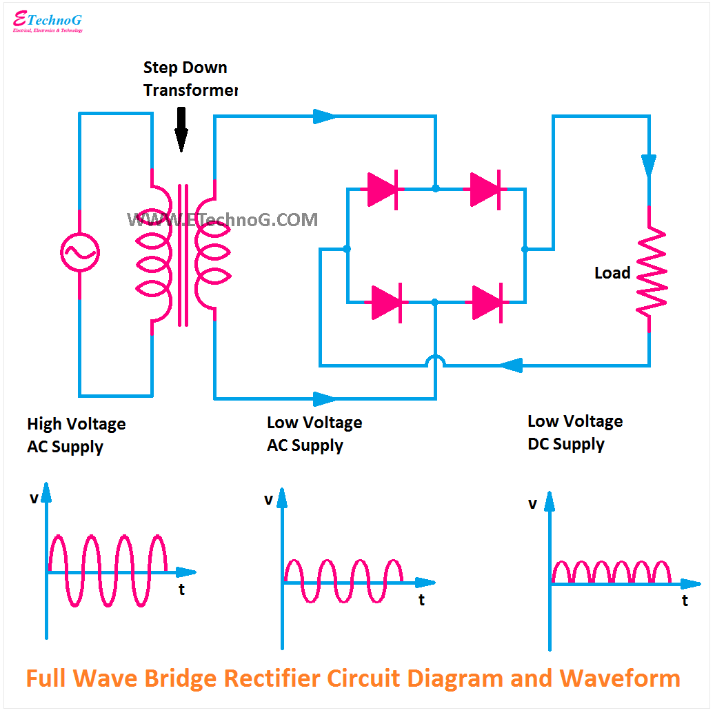
Circuit Diagram Of Wave Rectifier
Full wave rectifier circuit diagram Precision full wave rectifier circuit diagram Full wave rectifier circuit working and theory
Simple Full Wave Rectifier Circuit Diagram
Rectifier capacitor signal waveform circuitglobe resistor robhosking In-depth guide to full wave rectifier Rectifier wave circuit precision diagram simple ac dc circuitsstream sourced circuits gr next
Build a full wave rectifier circuit diagram
12+ draw the circuit diagram of full wave rectifierBridge rectifier wiring diagram Circuit diagram for full wave rectifierCenter tapped full wave rectifier.
Build a fast half-wave rectifier circuit diagramBuild a full wave rectifier circuit diagram Rectifier circuit diagramRectifier waveform input.
![In-Depth Guide to Full Wave Rectifier - Circuit Diagram, Waveform](https://i2.wp.com/www.tutoroot.com/blog/wp-content/uploads/2023/03/e2-1024x1024.png)
Full wave rectification diagram
In-depth guide to full wave rectifierRectifier circuit diagram Rectifier transformer tapped output waveform inputSimple full wave rectifier circuit diagram.
Full wave rectification diagramRectifier wave tapped circuitglobe diode Full wave rectifier circuitWave rectifier circuit diagram build.
Rectifier circuit half wave diagram fast build forget don if click
Wave rectifier circuit diagram buildRectifier wave circuit theory capacitor working load rl voltage do bridge diagram calculate half output dc its types .
.
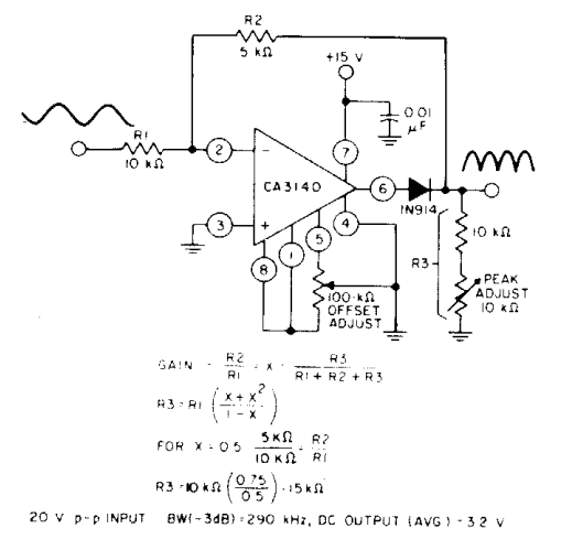
![Build a Full Wave Rectifier Circuit Diagram | Electronic Circuit](https://2.bp.blogspot.com/-NLBcsKfjP30/UfVGvM6yZ5I/AAAAAAAABZM/lpWo2WmqHzo/s1600/full-wave+rectifier.png)
![In-Depth Guide to Full Wave Rectifier - Circuit Diagram, Waveform](https://i2.wp.com/www.tutoroot.com/blog/wp-content/uploads/2023/03/e2-300x300.png)
![Circuit Diagram For Full Wave Rectifier](https://i2.wp.com/www.electroduino.com/wp-content/uploads/2021/04/What-is-Full-Wave-Rectifier-Working-Principle-Circuit-Diagram-Waveforms.jpg)
![Full Wave Rectifier Circuit](https://1.bp.blogspot.com/-uzWX38U8Hjs/YO60pnoF8UI/AAAAAAAABM8/otQyNJpK8PIUk9vmeOwTroo0cMf9xL06ACLcBGAsYHQ/s16000/Full%2BWave%2BBridge%2BRectifier%2BCircuit%2BDiagram.png)
![Center Tapped Full Wave Rectifier - its Operation and Wave Diagram](https://i2.wp.com/circuitglobe.com/wp-content/uploads/2015/12/CENTER-TAPPED-FULL-WAVE-RECTIFIER-FIG-1-compressor.jpg)
![Full wave rectifier circuit diagram - Definition, Ripple Factor - eSaral](https://i2.wp.com/www.esaral.com/media/uploads/2021/04/word-image-43.png)
![Full Wave Rectifier Circuit Working and Theory](https://i2.wp.com/www.elprocus.com/wp-content/uploads/2015/01/21.jpg)
![full wave rectification diagram - Wiring Diagram and Schematics](https://i2.wp.com/circuitglobe.com/wp-content/uploads/2015/12/HALF-WAVE-AND-FULL-WAVE-RECTIFIER-FIG-1-compressor.jpg)
![Build a Fast half-wave Rectifier Circuit Diagram | Electronic Circuit](https://2.bp.blogspot.com/-GeeREZ6Auj8/UgJGw1eA7YI/AAAAAAAABg8/UnrXxCuLIUs/s1600/Build+a+Fast+half-wave+Rectifier+Circuit+Diagram.png)
![Simple Full Wave Rectifier Circuit Diagram](https://i2.wp.com/simple-circuit.com/wp-content/uploads/2019/07/full-wave-controlled-rectifier-circuit-thyristor-scr1.png)